
Список товаров
Связаться с нами
Электронная почта: qiao@hvtest.cc
Мобильный: +8615871365102
What's app: +8615871365102
-
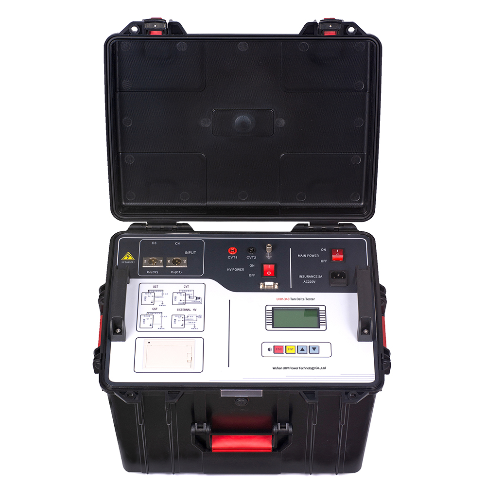
Why do we need to pay attention to automatic dielectric loss testers?
2026-07-03In the field of power equipment maintenance and quality inspection, "dielectric loss" is an unavoidable indicator. It directly reflects the performance of insulation materials and is related to the safe operation of power equipment. What does this somewhat technical term actually mean? What other factors can affect it? Today we will talk about the automatic dielectric loss tester and see what role it plays in ensuring power safety.Dielectric loss, in simple terms, refers to the phenomenon in which a dielectric converts a portion of electrical energy into thermal energy under the action of an electric field. Imagine applying a voltage to an insulating material, which is not completely leakage free. Some of the energy will be lost in the form of heat, which is known as dielectric loss. The lower the loss value, the better the insulation performance of the material, and the less likely it is to age and be damaged.There are many factors that affect dielectric loss, including:Temperature: A
БОЛЕЕ -
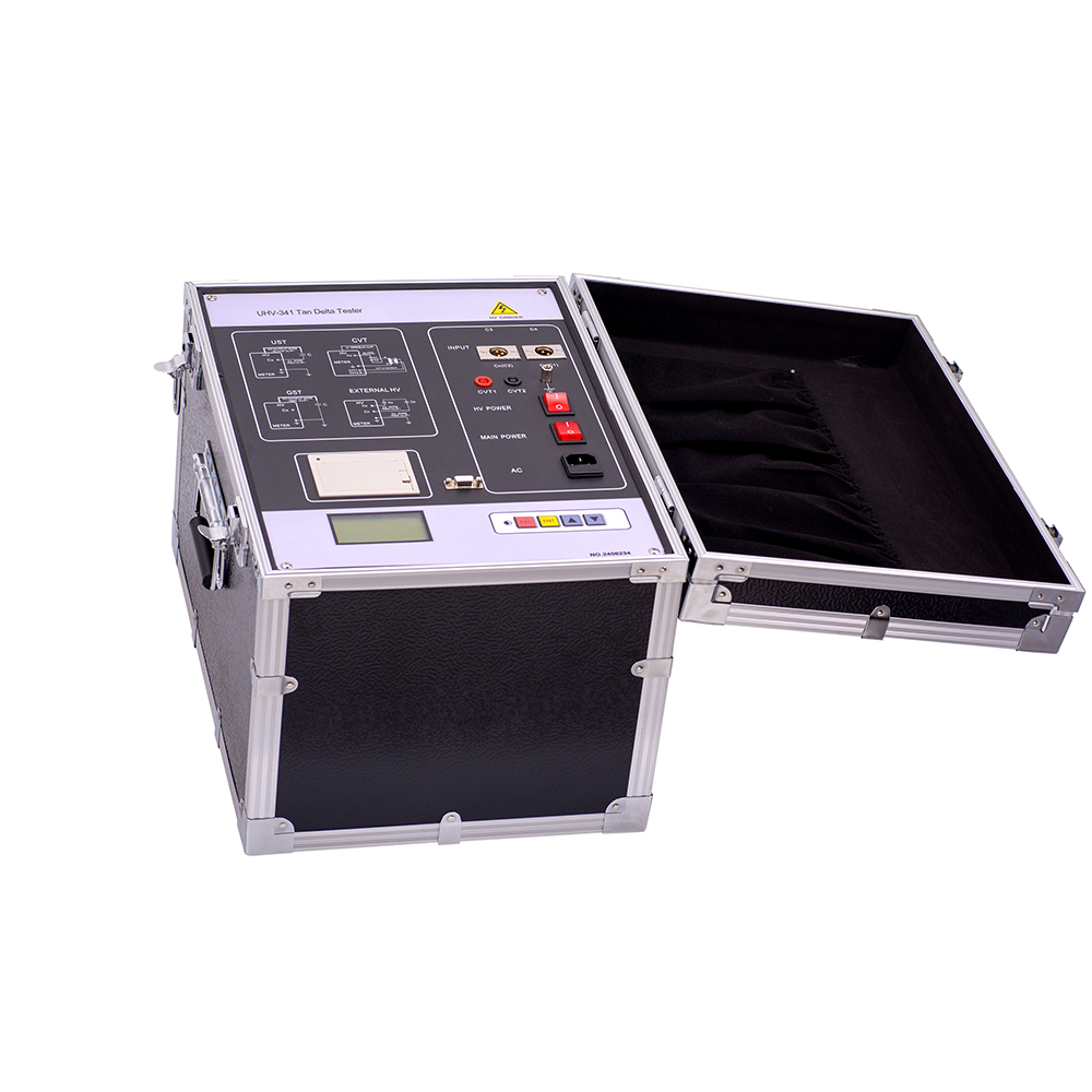
Why pay attention to dielectric loss measuring instruments? What exactly is it measuring?
2026-07-03In the field of power equipment testing, the term "dielectric loss" may sound a bit specialized, but it is a key indicator for measuring the aging degree of insulation materials and judging the health status of equipment. Simply put, dielectric loss refers to a portion of the energy loss in an insulating medium under the action of an alternating electric field. This energy will dissipate in the form of heat, and long-term accumulation will not only affect the normal operation of the equipment, but may also lead to insulation breakdown and cause safety accidents. So, accurately measuring dielectric loss is like giving a "health check" to electrical equipment.There are many factors that can affect dielectric loss, such as temperature, humidity, electric field strength, the properties of the insulation material itself, and the service life of the equipment. For example, a humid environment can significantly increase the dielectric loss of insulation materials. As the equipment ages, the i
БОЛЕЕ -
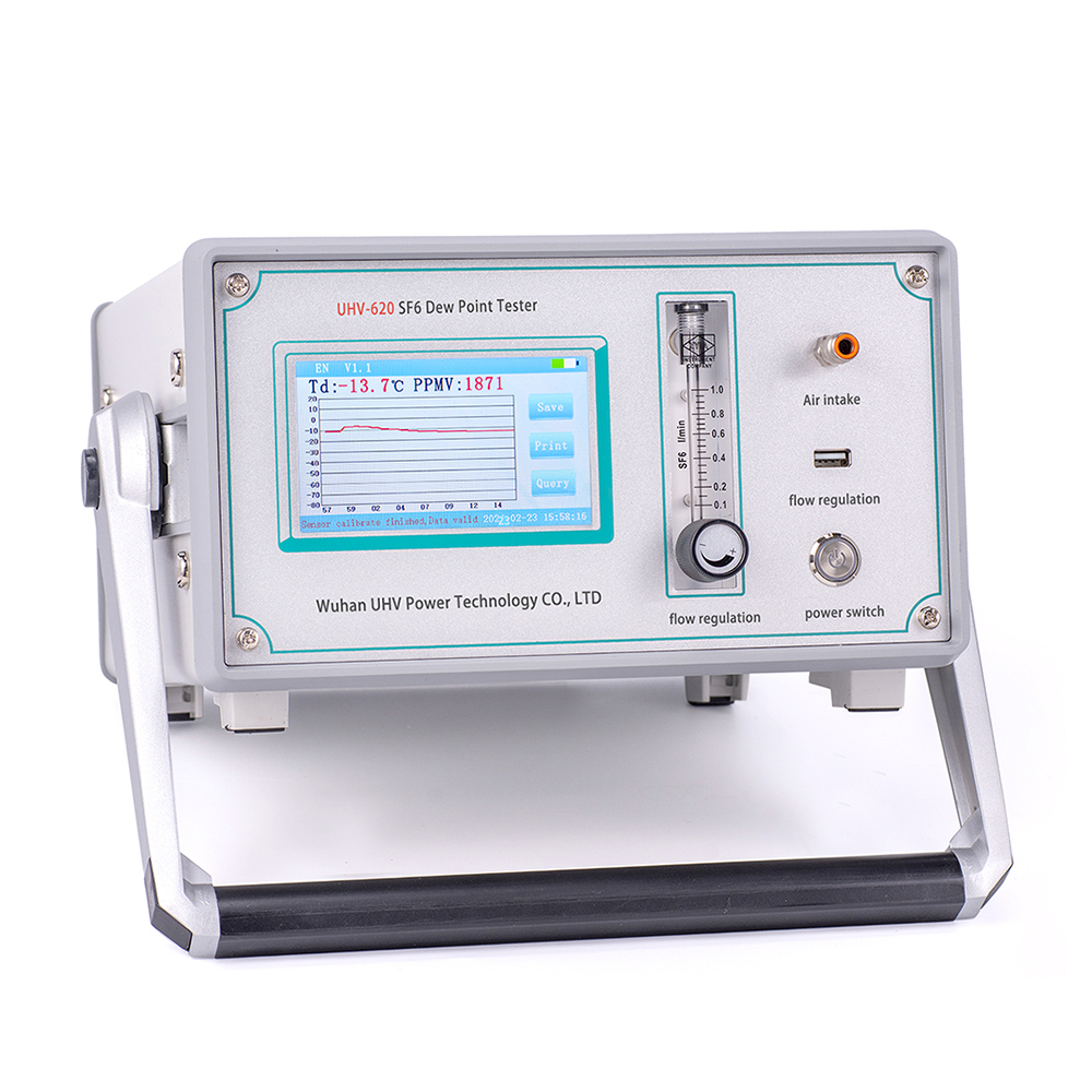
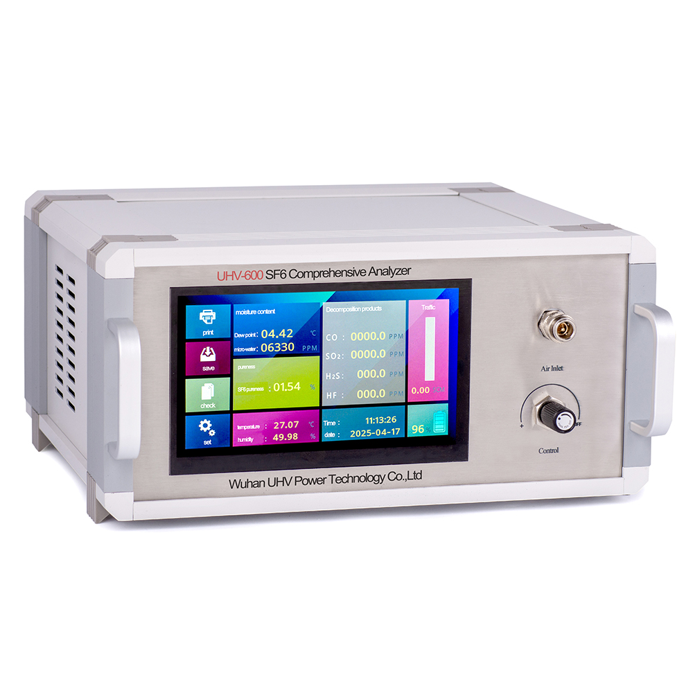
What are the safety hazards of SF6 gas micro water exceeding the standard?
2026-07-02SF6 gas, also known as sulfur hexafluoride, is a very important insulating medium in the power industry. It plays a crucial role in key power equipment such as substations. SF6 gas has high environmental requirements, among which the micro water content is a key indicator. What invisible "troubles" will SF6 gas micro water exceeding the standard bring?The importance of SF6 gas micro waterSimply put, the SF6 gas micro water tester is a "health manager" used to detect the moisture content in SF6 gas. SF6 gas itself has excellent insulation and arc extinguishing properties, but once moisture in the air enters the SF6 gas environment, the situation may become complicated. Micro water refers to the water vapor in SF6 gas that is invisible to the naked eye. Excessive micro water content, like adding blockage to SF6 gas, will greatly weaken its insulation ability and may cause a series of equipment problems.Factors affecting SF6 gas micro waterEquipment sealing: This is the most direct factor
БОЛЕЕ -
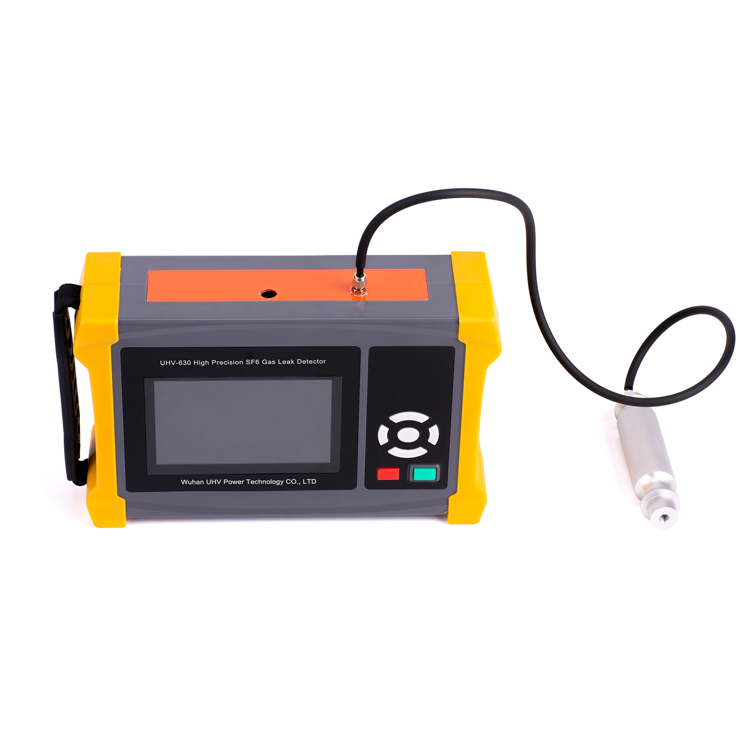
SF6 qualitative leak detector: precise positioning, safeguarding power safety
2026-07-01Have you ever been troubled by the leakage of SF6 gas in power equipment? SF6 qualitative leak detector, as an indispensable "detective" in power operation and maintenance, can help us quickly identify the source of problems. It is an SF6 leak detection device that can sensitively detect small leakage points of SF6 gas.Why do SF6 gas leaks need to be detected in a timely manner?SF6 gas, also known as sulfur hexafluoride, is widely used in high-voltage switchgear due to its excellent insulation performance and arc extinguishing ability. Once a leak occurs, it will not only reduce the insulation level of the equipment and affect the stability of power supply, but also have an impact on the environment, as SF6 is a greenhouse gas. Therefore, SF6 gas leak detection is particularly important.How does SF6 qualitative leak detector work?This type of SF6 leak detection instrument usually uses technical principles such as infrared absorption or mass spectrometry. When the instrument approaches
БОЛЕЕ -
Improving Power Grid Safety: How SF6 Gas Detectors Safeguard the Stable Operation of Equipment
2026-07-01SF6 gas plays a crucial role. It is widely used in high-voltage switchgear due to its excellent insulation and arc extinguishing performance. Once SF6 gas leaks, it not only affects the normal operation of equipment, but may also have an impact on the environment. Therefore, accurate and timely detection of SF6 gas has become a key link in ensuring the safety of the power grid.What is SF6 gas detection?SF6 gas, also known as sulfur hexafluoride, is a colorless, odorless, and non-toxic gas. In high-voltage electrical equipment, it is used as an insulating medium to effectively prevent electrical faults from occurring. SF6 gas detection, as the name suggests, is the use of professional instruments and equipment to monitor the concentration, density, or leakage points of SF6 gas inside the equipment. This is like conducting a "health check" on power grid equipment to ensure the stability of its internal environment.Factors affecting SF6 gas detectionEquipment sealing: This is the most dir
БОЛЕЕ -
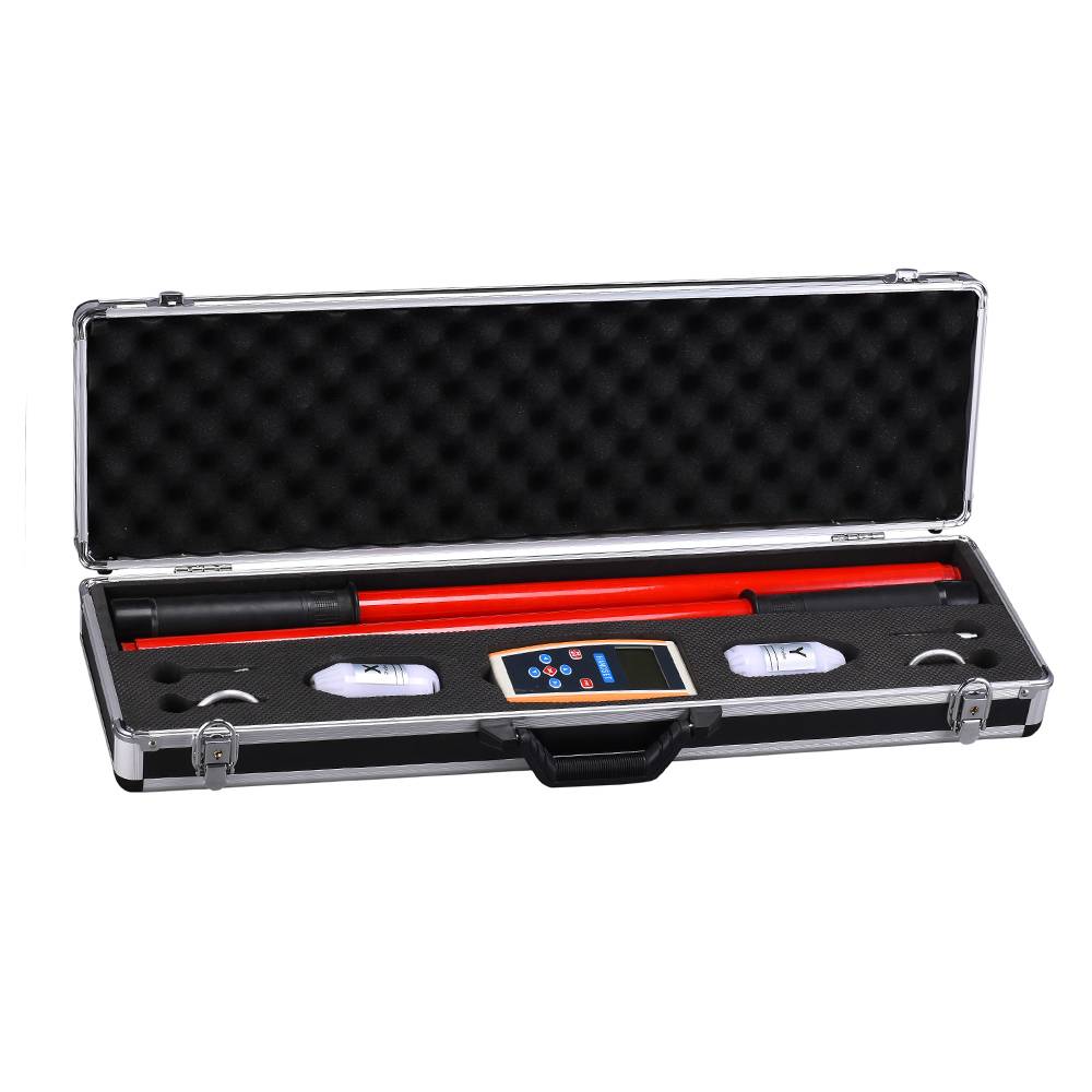
The key to improving the safety of 10kV high-voltage line operation: understanding high-voltage phase analyzer
2026-07-01In the operation and maintenance of power systems, the 10kV high‑voltage phase tester plays an essential role. It is an instrument used to check, in a de‑energised state, whether the phases of two or more high‑voltage power sources (such as incoming and outgoing lines in a substation) are consistent. Ensuring phase consistency is the fundamental safeguard against equipment damage, grid disruption, or even serious accidents caused by incorrect phase connections.Why is phase consistency so important?To put it simply, imagine wiring a three‑phase motor. If the phase sequence of the three live wires is disrupted, the motor's rotation direction will be wrong – at best it will fail to operate properly, and at worst it may burn out. In a complex 10kV high‑voltage grid, such "phase misconnection" can lead to regional blackouts, causing enormous impacts on production and daily life. Therefore, every high‑voltage line operation – especially maintenance, paralleling, and similar procedures –
БОЛЕЕ -
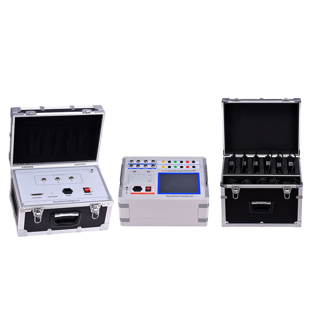
High voltage switch comprehensive tester: a key equipment for efficient detection
2026-06-30Behind the safe and stable operation of the power system, there are many key equipment that silently contribute, and the high-voltage switch comprehensive tester is one of them. It is like a "health inspector" for the power system, evaluating various performance indicators of high-voltage switches through a series of precise tests to ensure that they can reliably "close" and "disconnect" at critical moments.What is a high-voltage switch comprehensive tester?Simply put, the high-voltage switch comprehensive tester is a portable instrument specifically designed to test the electrical performance of high-voltage circuit breakers (high-voltage switches). It can complete the measurement of various electrical parameters during the closing and opening process of the circuit breaker at once, such as closing/opening time, synchronicity, rebound frequency, bounce time, three-phase asymmetry, etc. These parameters are directly related to the accuracy and reliability of the operation of high-volta
БОЛЕЕ -
What factors affect the accuracy of high-voltage cable fault detection?
2026-06-29In the power system, high-voltage cables play a crucial role as the "arteries" that transport electricity. Like any complex device, high-voltage cables can also malfunction. Once a malfunction occurs, it not only affects the stability of power supply, but may also pose safety hazards. Timely and accurate identification of the fault point is the key to ensuring the safe operation of the power system. What factors can affect the accuracy of high-voltage cable fault detection?The 'behind the scenes' driving force that affects fault detectionThe characteristics of the cable itself: High voltage cables of different materials and structures will also have different electrical characteristics for faults. For example, faults caused by insulation aging, mechanical damage, overheating, and other reasons may have different signal characteristics.Fault types: There are various types of faults in high-voltage cables, including grounding faults, short circuit faults, and disconnection faults
БОЛЕЕ -
Mastering the "ears and eyes" of high-frequency partial discharge: How does a high-frequency partial discharge detector protect power equipment?
2026-06-29On the stage of safe operation of power equipment, high-frequency partial discharge detectors play a crucial role as "guardians". Many friends may feel unfamiliar with this name, but what exactly is it sacred for? Simply put, it is like the "high-tech stethoscope" and "golden eyes" on electrical equipment, capable of capturing subtle electrical abnormalities that are difficult for the naked eye or ordinary ears to detect - that is, partial discharge.What is partial discharge?Partial discharge is a partial discharge phenomenon that occurs inside solid, liquid, or gas insulating media, but has not yet developed into complete breakdown. Although it may appear 'localized', over time, like boiling a frog in warm water, it will gradually erode the insulation material, ultimately leading to serious equipment malfunctions and even fires. Think about it, this is like a hidden "little worm" in the power system. If not detected in time, the consequences can be unimaginable.Factors affecti
БОЛЕЕ -
Fuzzy judgment: how to accurately measure the "health status" of high-voltage switches?
2026-06-29In the power system, high-voltage switches are key equipment to ensure the safe and stable operation of power transmission. Every "opening and closing" action of them affects the electrical safety of billions of users. The internal structure of high-voltage switches is complex, and various "minor problems" are inevitable during long-term operation. If not detected and dealt with in a timely manner, the consequences will be unimaginable. How can we accurately understand the "health status" of high-voltage switches by observing, hearing, and asking questions? The answer lies in using a high-voltage switch characteristic tester.What is a high-voltage switch characteristic tester?Simply put, a high-voltage switch characteristic tester is an instrument specifically designed to measure and analyze the electrical characteristics of high-voltage switches. It is like an experienced "doctor" who can conduct a series of professional tests to "examine" high-voltage switches and evaluate whether th
БОЛЕЕ -
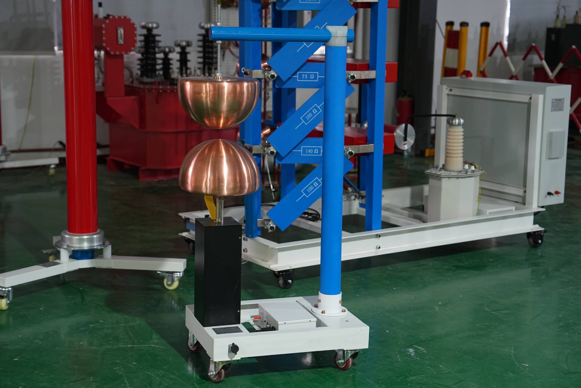
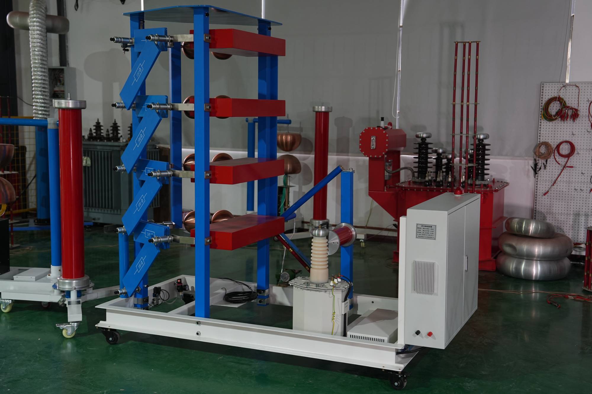
How is the 10000 volt 'lightning' refined? Lightning impulse voltage generator test device
2026-06-25Have you ever thought about how the seemingly unattainable "lightning" in our daily lives can be "reproduced" and studied in the laboratory? Behind this lies an important 'secret weapon' - the lightning impulse voltage generator test device. Today, let's talk about this guy that sounds a bit "high-end" and see how it actually works.What exactly is it?Simply put, the lightning impulse voltage generator test device is a device that can simulate the extremely high voltage generated during lightning moments. We know that when lightning strikes, the voltage can instantly soar to tens of thousands of volts or even higher. This huge energy impact is not a joke for power equipment. With this device, we can simulate lightning attacks in a controlled environment to test the tolerance of power equipment such as transformers and insulators.What factors will affect it?The charging voltage of the capacitor bank: This is the source of energy. The higher the voltage, the more energy is sto
БОЛЕЕ -
How to choose a suitable DC high-voltage generator? A practical shopping guide
2026-06-25When it comes to "DC high-voltage generators", many friends may think that they are far away from our lives, but in fact, they play a crucial role in multiple fields such as power testing and scientific research. Simply put, it is a device that can generate stable and controllable DC high voltage, and is the "behind the scenes hero" to ensure the safe operation of power equipment and the accuracy of scientific experiments.What is a DC high-voltage generator?A DC high-voltage generator, as the name suggests, is a high-voltage device that can output DC electricity. It can raise low voltage to several thousand volts or even higher DC voltage, and is widely used in insulation testing, cable withstand voltage testing, and performance testing of components in power systems. For example, in the factory inspection of high-voltage cables, it is necessary to use a DC high-voltage generator to simulate the high-voltage environment during operation, ensure that its insulation performance meets the
БОЛЕЕ -
Inventory of Lightning Impulse High Voltage Generators: Principles, Influencing Factors, and Application Prospects
2026-06-25In the field of safety testing for power systems and electronic equipment, lightning impulse high-voltage generators play a crucial role. You may often hear this word, but what exactly is it? Simply put, it is a device that can simulate the huge voltage and current surges generated instantly during lightning strikes. This kind of impact can cause serious damage to electrical equipment, so it is particularly important to understand and master how to deal with this "lightning strike".What is a lightning impulse high-voltage generator?A lightning impulse high-voltage generator, as the name suggests, is a device used to generate simulated lightning impulse waves. Lightning is a natural phenomenon whose voltage can reach millions of volts, current can reach hundreds of thousands of amperes, and it occurs in a very short time (microsecond level). In order to ensure that power equipment and electronic products can withstand such instantaneous overvoltage in practical use, strict withstand vol
БОЛЕЕ -
Why is high-voltage dielectric loss testing so important? Understanding these is essential to ensure electrical safety
2026-06-25Ensuring the safe and stable operation of equipment is of paramount importance in the power system. For many high-voltage electrical equipment, such as transformers, mutual inductors, etc., in addition to paying attention to their insulation performance, we also need to understand a key parameter - dielectric loss. What is the purpose of the high-voltage dielectric loss testing device? Why is it so important? Today we will talk about this topic.What is high voltage dielectric loss?Simply put, dielectric loss refers to the energy loss inside the dielectric under the action of an electric field. This energy will be converted into thermal energy, which may cause equipment overheating, accelerate insulation aging, and even lead to breakdown accidents in the long run. The dielectric loss coefficient (usually represented by tan δ) is an indicator of the magnitude of this energy loss. In the insulation diagnosis of high-voltage electrical equipment, tan δ is a very important reference value.W
БОЛЕЕ -
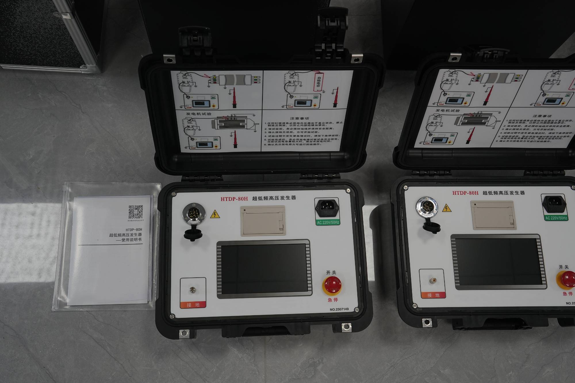
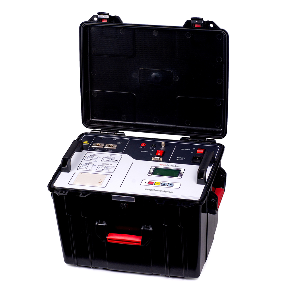
Why do we need to pay attention to very low frequency withstand voltage testing? The key to improving the safety of power equipment!
2026-06-17In the field of safety testing for power equipment, very low frequency withstand voltage testing plays a crucial role. You may be curious, what does this sound like a bit of technical expertise mean? How does it safeguard our daily electricity safety? Simply put, very low frequency withstand voltage test is a method of testing the insulation performance of power equipment using lower frequency AC voltage. Compared with traditional power frequency (50Hz) withstand voltage tests, very low frequency withstand voltage tests have shown unique advantages in many aspects, especially in detecting insulation aging and defects of large generators, transformers and other high-voltage equipment.Why choose 'very low frequency'?This is because as the operating years of power equipment increase, their insulation materials will gradually age, resulting in subtle cracks or moisture. The traditional power frequency withstand voltage test may cause rapid breakdown of these already fragile insulat
БОЛЕЕ -

Is the clamp meter more reliable than you imagine when measuring grounding resistance?
2026-06-17Grounding is a crucial link in ensuring electrical safety and reliable operation of equipment. To evaluate the effectiveness of the grounding system, the measurement of grounding resistance is particularly crucial. Today, let's talk about a very convenient measuring tool in practical applications - clamp type grounding resistance meter.What is a clamp type grounding resistance meter?Simply put, a clamp type grounding resistance meter is an instrument that can directly measure grounding resistance without disconnecting the grounding wire. It utilizes the principle of electromagnetic induction to quickly obtain a reading of the grounding resistance by clamping the grounding wire without damaging the original grounding circuit. Compared to traditional grounding resistance testers, this greatly simplifies the operation process, especially suitable for situations where there are many grounding electrodes that are difficult to disconnect one by one.What are the factors that affect ground
БОЛЕЕ -
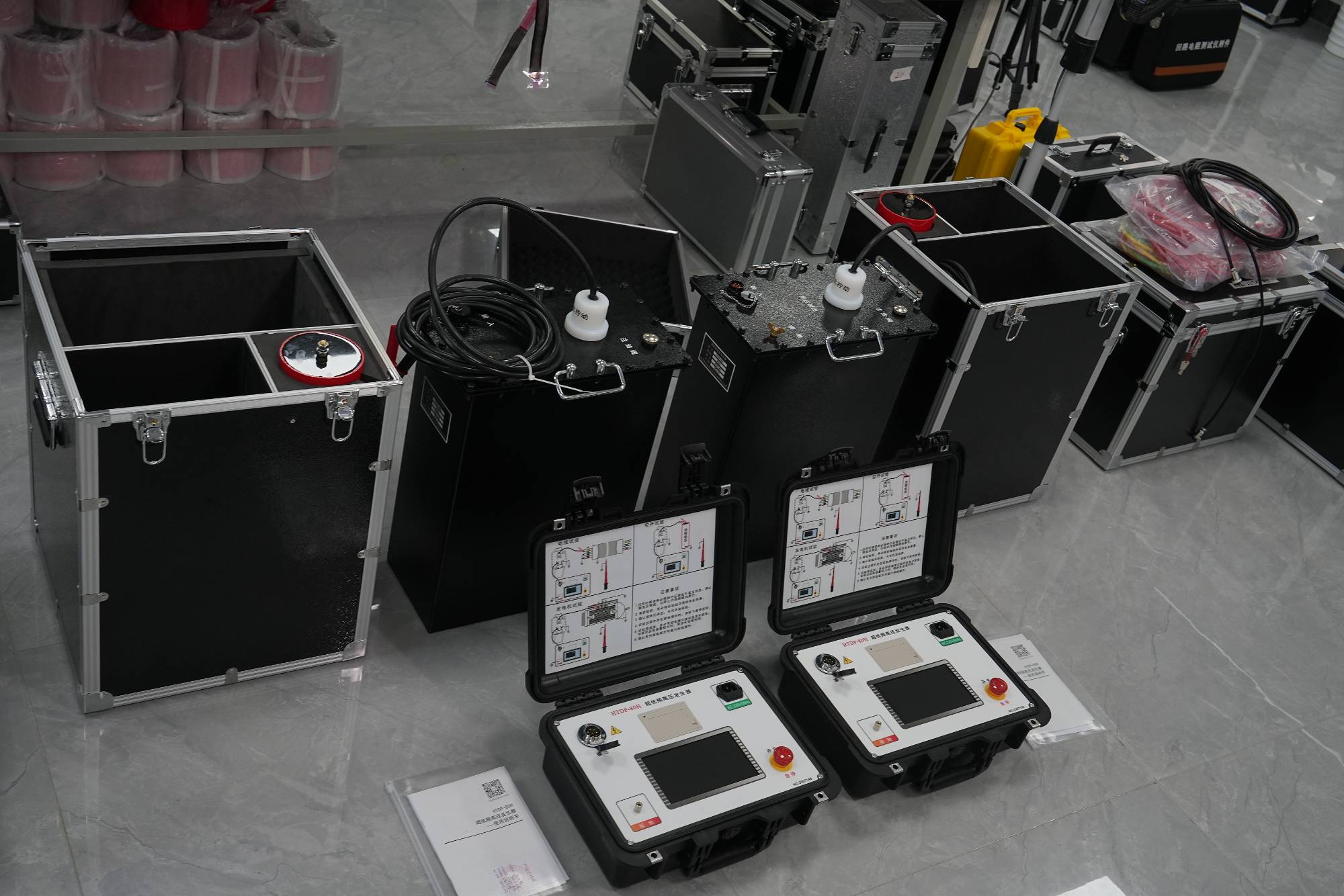
Why does your device need a "very-low frequency withstand voltage test"?
2026-06-17The detection of insulation performance is crucial in the safe operation of power equipment. The very-low frequency withstand voltage tester is the key "medical examiner" to ensure this performance. It conducts a gentle yet effective "physical examination" of high-voltage equipment to ensure its safety and reliability even under harsh operating conditions.What is very-low frequency withstand voltage test?Simply put, very-low frequency withstand voltage testing is a method of testing the withstand voltage capability of insulation materials such as power equipment insulation cardboard and insulation oil by applying a specific low-frequency high voltage. Compared with traditional power frequency withstand voltage testing, the advantages of very-low frequency testing are:Reduce the impact of capacitance effect: Most high-voltage equipment has a large capacitance, which can generate huge capacitance currents during testing at power frequency, requiring extremely high requirements for testin
БОЛЕЕ -
The 'invisible killer' of grounding resistance testing? How many of these factors do you know?
2026-06-17In the field of power safety, the importance of "grounding" is self-evident. It is like an invisible guardian, ensuring the normal operation of equipment and protecting our personal safety. To verify whether this' guardian deity 'is qualified, it cannot do without a lightning protection grounding resistance tester. But did you know? The quality of the results of this small testing instrument is not only a problem with the instrument itself, but also hides many "invisible killers" behind it.Why is grounding resistance important?We need to understand that grounding resistance refers to the resistance encountered by current flowing from the grounding body into the earth. The smaller the resistance, the faster and more thorough the current discharge. Why is this important?Lightning protection: The lightning rod is connected to the ground to safely guide the huge current generated by lightning into the ground, avoiding damage to buildings and equipment. A small grounding resistance
БОЛЕЕ -
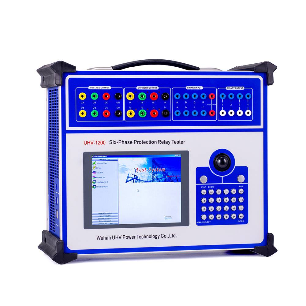
Mastering Relay Protection Tester: The 'Gatekeeper' for Safe Operation of Power Systems
2026-06-15The power system is like the "neural network" of a city, and relay protection devices are indispensable "safety switches" in this network. They are responsible for quickly and accurately cutting off power in the event of a power line failure, avoiding wider damage and danger. How can we ensure that these 'goalkeepers' always maintain their best form? The answer is - relying on relays to protect the tester.What is a relay protection tester?Simply put, a relay protection tester is a specialized equipment used to test and debug the performance of various protective relays in power systems. It can simulate current and voltage signals under various operating conditions, and accurately measure and evaluate the action characteristics of the protection device (such as accuracy of action, reaction speed, etc.) based on preset parameters. This is like giving regular physical examinations and simulated training to "goalkeepers" to ensure that they can respond "steadily, accurately, and ru
БОЛЕЕ -
Comparing three commonly used methods for measuring dielectric loss, which measuring instrument is more suitable for you?
2026-06-15In the field of power systems and high-voltage electrical appliances, the term "dielectric loss" is undoubtedly familiar to everyone, and it is a key indicator for measuring the performance of insulation materials. Simply put, dielectric loss refers to the loss of electrical energy converted into thermal energy. The lower the loss, the better the insulation performance of the material. How can we accurately measure this' loss'? Today we will talk about the "automatic anti-interference precision dielectric loss measuring instrument" and its measurement technology, helping you clarify your thinking and find the most suitable measurement solution for yourself.Understanding 'dielectric loss': not just a numberLet's first break down the name "Automatic Anti Interference Precision Dielectric Loss Measuring Instrument".Dielectric loss: When a medium (such as an insulating material) is placed in an electric field, a portion of the electrical energy is converted into thermal
БОЛЕЕ


